
TM 5-3805-298-23-4
0371
REMOVAL CONTINUED
NOTE
Tag and mark hoses and fittings to aid installation.
Cap or plug hose ends and fittings to protect against contamination.
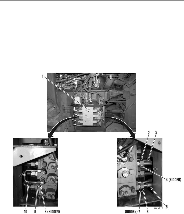
9. Loosen two tube nuts (Figure 6, Item 9) and remove tube (Figure 6, Item 10) and two O-rings (Figure 6, Item 8)
from main control valve (Figure 6, Item 1). Discard O-rings.
10. Loosen two tube nuts (Figure 6, Item 6) and remove two hoses (Figure 6, Item 5) and O-rings (Figure 6, Item 7)
from main control valve (Figure 6, Item 1). Position hoses aside and discard O-rings.
11. Loosen four tube nuts (Figure 6, Item 2) and remove four tubes (Figure 6, Item 3) and O-rings
(Figure 6, Item 4) from main control valve (Figure 6, Item 1). Discard O-rings.
Figure 6. Hoses and Tubes.
0371