
TM 5-3805-298-23-4
0373
REMOVAL CONTINUED
NOTE
Tag and mark hoses and fittings to aid installation.
Cap or plug hose ends and fittings to protect against contamination.
Note position and orientation of fitting.
Combination tilt relief valve sits on a dowel pin.
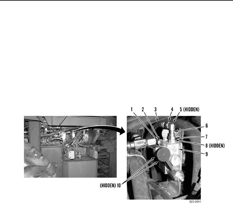
3. Loosen three tube nuts (Figure 3, Item 4) and remove three hoses (Figure 3, Items 3 and 10) and O-rings
(Figure 3, Item 5) from combination tilt relief valve (Figure 3, Item 9). Discard O-rings
4. Loosen tube nut (Figure 3, Item 7) and remove fitting (Figure 3, Item 6) and O-ring (Figure 3, Item 8) from
combination tilt relief valve (Figure 3, Item 9). Discard O-ring.
5. Remove bolt (Figure 3, Item 1), washer (Figure 3, Item 2), and combination tilt relief valve (Figure 3, Item 9)
from machine.
Figure 3. Combination Tilt Relief Valve Hoses.
0373