
TM 5-3805-298-23-4
0373
INSTALLATION CONTINUED
NOTE
Install hoses as noted during removal.
Remove caps from hoses and fittings prior to installation.
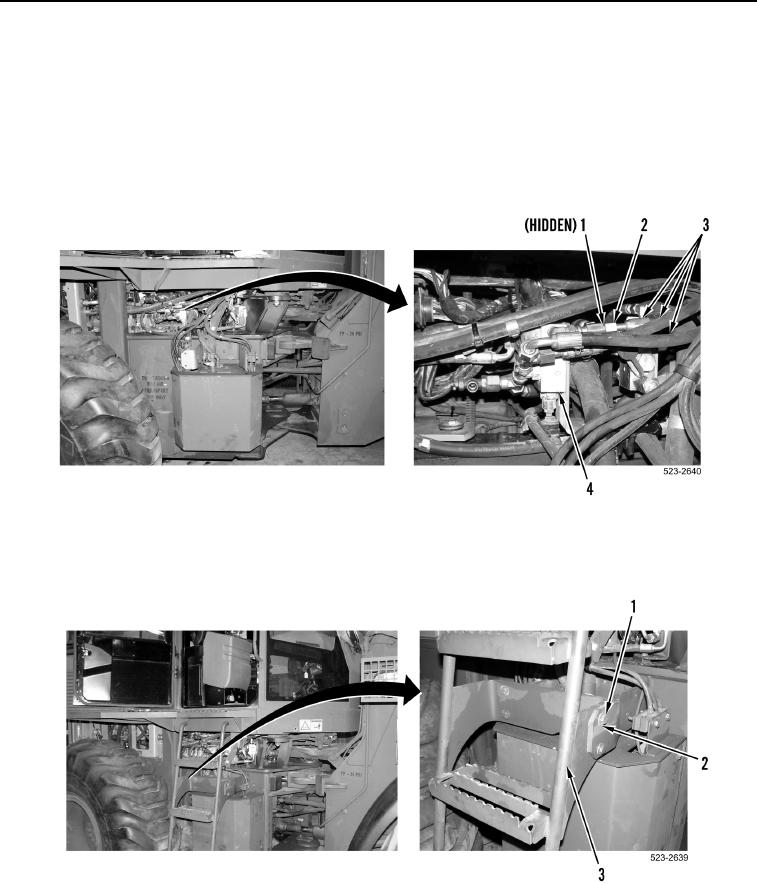
6. Install three new O-rings (Figure 6, Item 1), hoses (Figure 6, Item 3) and tube nuts (Figure 6, Item 2) on pilot oil
pressure reducing valve (Figure 6, Item 4).
Figure 6. Pilot Hoses.
0373
7. Install ladder (Figure 7, Item 3), four washers (Figure 7, Item 2), and bolts (Figure 7, Item 1) on machine.
Figure 7. Ladder.
0373
END OF TASK