
TM 5-3805-298-23-4
0380
REMOVAL CONTINUED
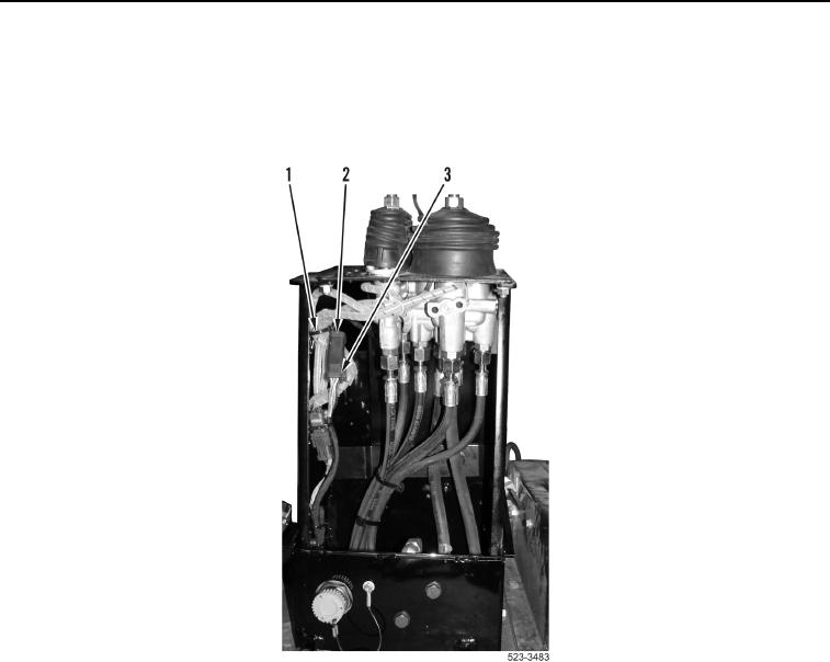
4. Remove tiedown strap (Figure 3, Item 1) and disconnect directional and downshift switches wiring harness
connector (Figure 3, Item 2) from lower cab wiring harness connector (Figure 3, Item 3). Discard tiedown strap.
5. Remove directional and download switches wiring harness (weatherproof) connector (Figure 3, Item 2) from
directional and downshift switches wiring harness (WP 0174).
Figure 3. Switches Connection.
0380