
TM 5-3805-298-23-4
0379
INSTALLATION CONTINUED
NOTE
Install control handles as noted during removal.
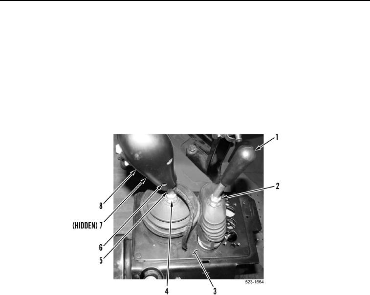
11. Install control rod (Figure 11, Item 5) on operator console (Figure 11, Item 3) and tighten jam nut (Figure 11,
Item 4).
12. Install direction and downshift control handle (Figure 11, Item 8) and two allen screw (Figure 11, Items 6 and 7)
on control rod (Figure 11, Item 5).
13. Install clamshell control handle (Figure 11, Item 1) on operator console (Figure 11, Item 3) and tighten jam nut
(Figure 11, Item 2).
Figure 11. Control Handles.
0379