
TM 5-3805-298-23-4
0380
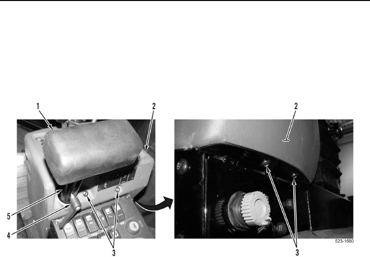
INSTALLATION CONTINUED
NOTE
Two bolts are located at top rear and two bolts are located at bottom front of operator
console.
7. Install operator console cover (Figure 6, Item 2) and four bolts (Figure 6, Item 3) on machine.
8. Install arm rest (Figure 6, Item 1) and control lever (Figure 6, Item 4) on support post (Figure 6, Item 5).
Figure 6. Arm Rest and Operator Console Cover.
0380