
8
TM 5-3805-298-23-4
FIELD MAINTENANCE
-
DIRECTION AND DOWNSHIFT SWITCH REPLACEMENT
038
0
Removal, Cleaning and Inspection, Installation
INITIAL SETUP
References
Tools and Special Tools
0
0
Tool Kit, General Mechanic's
WP 0174
0
(WP 0431, Item 162)
0
Equipment Conditions
0
Socket Driver, Torx, 3/8" Drive, T-30
Machine parked (TM 5-3805-298-10)
(WP 0431, Item 125)
0
0
Tool, Wedge Removal
Estimated Time to Complete
0
(WP 0431, Item 164)
0
1.0 Hr
0
Materials/Parts
0
Rag, Wiping (WP 0430, Item 27)
0
Tag, Marker (WP 0430, Item 35)
0
Tiedown Strap, Electrical Components
(WP 0430, Item 40)
0
REMOVAL
000380
NOTE
If removing operator console cover for wiring harness connector access, perform steps 1
through 3 only.
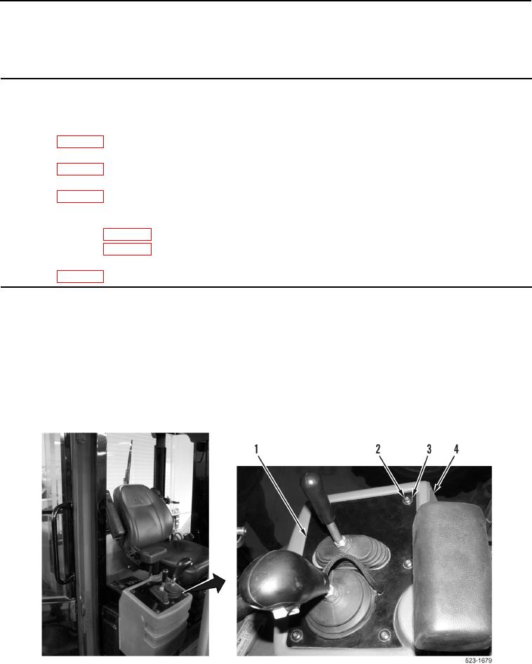
1. Remove six bolts (Figure 1, Item 2), washers (Figure 1, Item 3) and plate (Figure 1, Item 1) from operator
console (Figure 1, Item 4).
Figure 1. Pilot Valve Cover.
0380