
TM 5-3805-298-23-4
0380
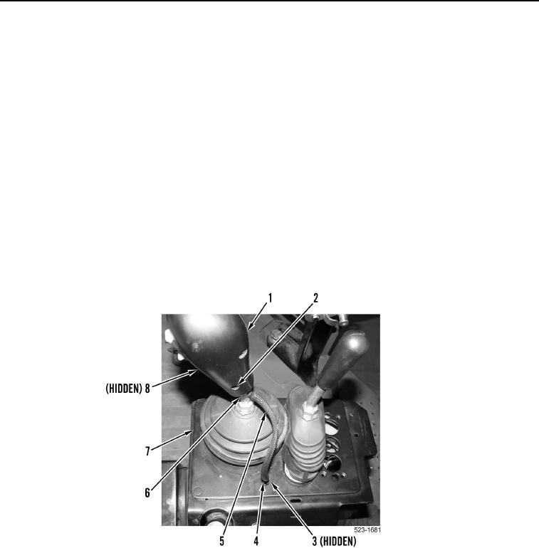
REMOVAL CONTINUED
NOTE
Directional and downshift control handle contains two screws. Cross slotted screw holds
directional and downshift control handle together. Allen screw holds directional and
downshift control handle to control rod.
Note location and orientation of control handle to aid installation.
6. Remove two allen screws (Figure 4, Items 2 and 8) and directional and downshift control handle (Figure 4,
Item 1) from control rod (Figure 4, Item 6). Position directional and downshift control handle aside.
NOTE
Note position and orientation of tiedown straps to aid installation.
7. Remove tiedown straps (Figure 4, Item 4) from directional and downshift switches wiring harness (Figure 4,
Item 5). Discard tiedown straps.
8. Remove directional and downshift switches wiring harness (Figure 4, Item 5)and grommet (Figure 4, Item 3)
from pilot valve assembly (Figure 4, Item 7).
Figure 4. Control Handle.
0380
END OF TASK
CLEANING AND INSPECTION
000380
Clean and inspect all parts IAW Electrical General Maintenance Instructions (WP 0174).
END OF TASK