
TM 5-3805-298-23-4
0392
REMOVAL
000392
NOTE
Note wiring harness routing to aid installation.
Tag and mark wiring harness connectors to aid installation.
Note position and quantity of tiedown straps to aid installation.
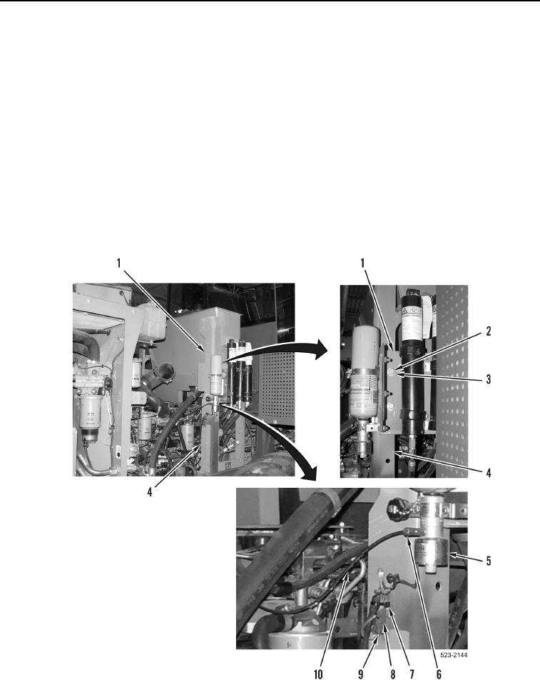
1. Remove tiedown strap (Figure 1, Item 7) from rear frame wiring harness connector (Figure 1, Item 8). Discard
tiedown strap.
2. Disconnect rear frame wiring harness connector (Figure 1, Item 8) from ether aid solenoid connector
(Figure 1, Item 9).
3. Loosen tube nut (Figure 1, Item 6) and remove ether line (Figure 1, Item 10) from ether valve (Figure 1,
Item 5). Position ether line aside.
4. Remove four bolts (Figure 1, Item 2), washers (Figure 1, Item 3) and accumulator panel (Figure 1, Item 1) from
hydraulic tank frame (Figure 1, Item 4). Position accumulator panel aside.
Figure 1. Accumulator Panel.
0392