
TM 5-3805-298-23-4
0392
REMOVAL CONTINUED
WARNING
DO NOT disconnect or remove any hydraulic system line or fitting unless engine is shut
down and hydraulic system pressure has been relieved. Tighten all connections before
applying pressure. Escaping hydraulic fluid under pressure can penetrate the skin,
causing injury to personnel.
At operating temperature, hydraulic oil is hot. Allow hydraulic oil to cool before removing
any hydraulic fitting.
Wear protective clothing and eye covering.
Lubricating/hydraulic oils can be very slippery. Immediately wipe up any spills. Failure to
follow this warning may result in injury or death to personnel.
Dispose of all fluids according to local regulations and mandates.
Failure to follow these warnings may result in injury to personnel.
NOTE
Tag and note location of hoses and connectors to aid installation.
Note location and quantity of tiedown straps to aid installation.
Cap hoses and fittings to prevent contamination.
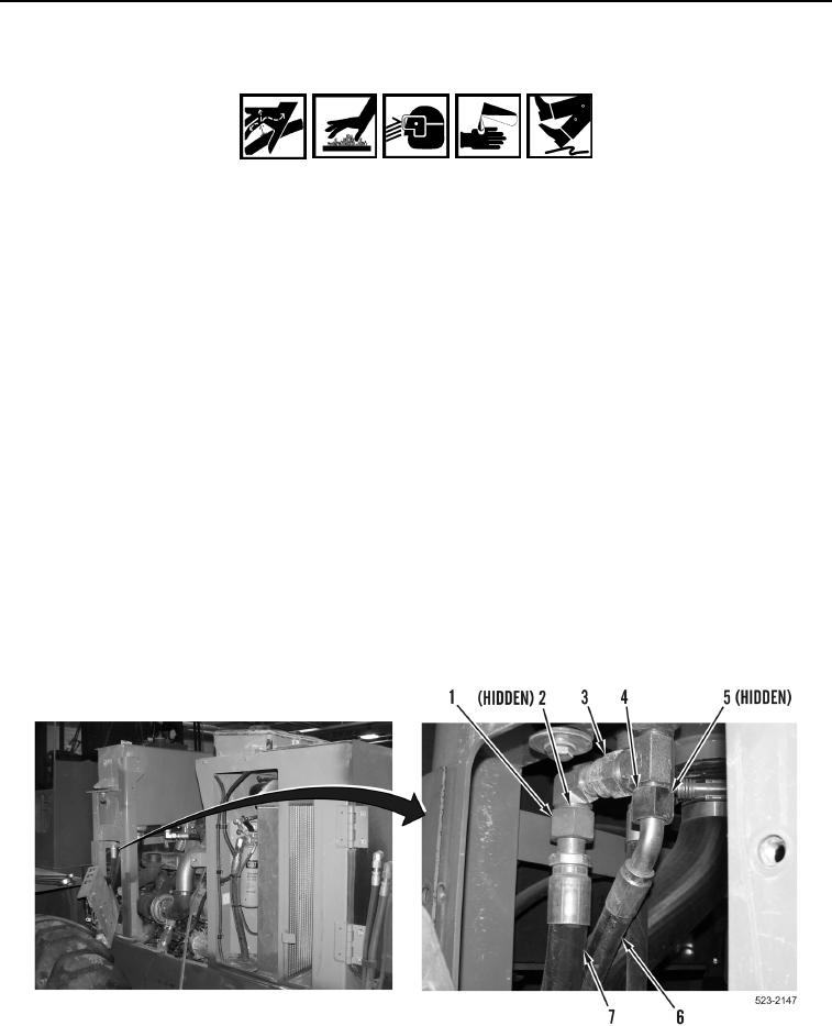
8. Loosen tube nut (Figure 4, Item 4) and remove hose (Figure 4, Item 6) and O-ring (Figure 4, Item 5) from fitting
(Figure 4, Item 3). Discard O-ring.
9. Loosen tube nut (Figure 4, Item 1) and remove hose (Figure 4, Item 7) and O-ring (Figure 4, Item 2) from fitting
(Figure 4, Item 3). Discard O-ring.
Figure 4. Left Side Hydraulic Tank Hoses.
0392