
TM 5-3805-298-23-4
0392
REMOVAL CONTINUED
NOTE
Note wiring harness routing to aid installation.
Note position of spacers to aid installation.
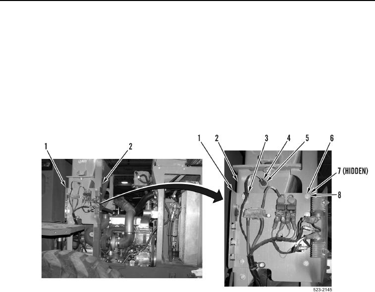
5. Disconnect engine wiring harness connector (Figure 2, Item 4) from hydraulic temperature sensor
(Figure 2, Item 5).
6. Remove four bolts (Figure 2, Item 6), washers (Figure 2, Item 8), ladder clip (Figure 2, Item 3), spacers
(Figure 2, Item 7) and panel (Figure 2, Item 1) from hydraulic tank frame (Figure 2, Item 2). Position panel
aside.
Figure 2. Panel.
0392