• Home
  • Download PDF
  • Order CD-ROM
  • Order in Print
Figure 5. Hydraulic Tank Supply Hoses.
Figure 7. Right Side Hydraulic Tank Hoses.

Field Maintenance Manual For 924H Wheel Loader -4 Page Navigation
  296    297    298    299    300  301  302    303    304    305    306  
img
.
TM 5-3805-298-23-4
0392
REMOVAL CONTINUED
NOTE
Tag and note location of hoses and connectors to aid installation.
Cap hoses and fittings to prevent contamination.
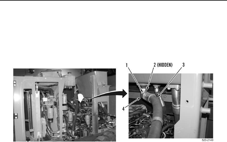
12. Loosen tube nut (Figure 6, Item 1) and remove hose (Figure 6, Item 3) and O-ring (Figure 6, Item 2) from fitting
(Figure 6, Item 4). Discard O-ring.
Figure 6. Gear Pump Supply Hoses.
0392
0392-7


Privacy Statement
Press Release
Contact

© Copyright Integrated Publishing, Inc.. All Rights Reserved.