
TM 5-3805-298-23-4
0392
REMOVAL CONTINUED
NOTE
Tag and note location of hoses and connectors to aid installation.
Cap hoses and fittings to prevent contamination.
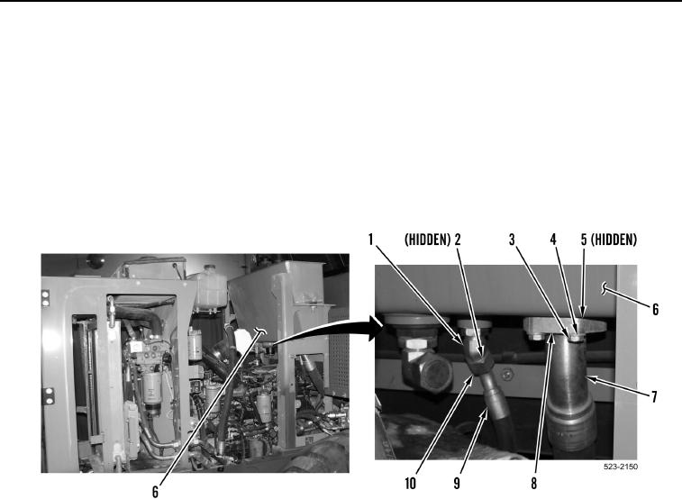
13. Loosen tube nut (Figure 7, Item 10) and remove hose (Figure 7, Item 9) and O-ring (Figure 7, Item 2) from
fitting (Figure 7, Item 1). Discard O-ring.
14. Remove four bolts (Figure 7, Item 3), washers (Figure 7, Item 4), two split flange clamps (Figure 7, Item 8),
hose (Figure 7, Item 7) and O-ring (Figure 7, Item 5) from hydraulic tank (Figure 7, Item 6). Discard O-ring
.
Figure 7. Right Side Hydraulic Tank Hoses.
0392