
TM 5-2420-231-23-1
0013
Table 1. Engine Does Not Crank or Cranks Slowly - Continued.
013
MALFUNCTION
TEST OR INSPECTION
CORRECTIVE ACTION
10. Using a digital multimeter, mea-
Engine Does Not Crank or
Resistance 5.0 Ohms or Less -
sure resistance between neutral
Proceed to step 11.
Cranks Slowly - Continued
relay wiring harness connector
Resistance Greater Than 5.0 Ohms -
(WP 0007, Figure 22) terminal 30
Replace front console wiring harness
and front console wiring harness
(WP 0162).
connector (WP 0007, Figure 24)
Proceed to Test Step 7.
terminal M7. Resistance should be
5.0 ohms or less.
11. Using a digital multimeter, test for
Continuity - Replace front console
continuity between neutral relay
wiring harness (WP 0162).
wiring harness connector (WP
Proceed to Test Step 7.
0007, Figure 22) terminal 30 and
No Continuity - Proceed to step 12.
machine ground. There should be
no continuity.
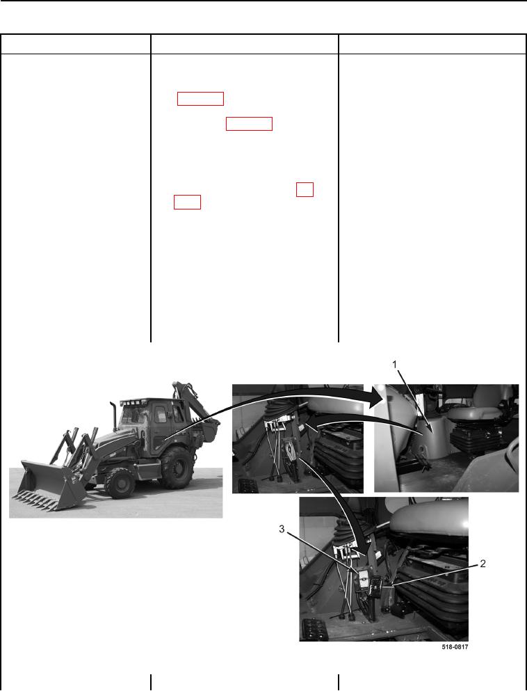
12. Remove front instrument panel
right-side cover (Figure 13, Item 1)
(WP 0176).
13. Disconnect side console wiring
harness connector (Figure 13,
Item 2) from rear main chassis wir-
ing harness connector (Figure 13,
Item 3).
Figure 13. Instrument Panel Right-Side Cover and Side Console Wiring Harness Connector.
0013