
TM 5-2420-231-23-1
0013
Table 1. Engine Does Not Crank or Cranks Slowly - Continued.
013
MALFUNCTION
TEST OR INSPECTION
CORRECTIVE ACTION
7. Using a digital multimeter, mea-
Engine Does Not Crank or
Resistance 5.0 Ohms or Less -
sure resistance between starter
Proceed to step 8.
Cranks Slowly - Continued
relay wiring harness connector
Resistance Greater Than 5.0 Ohms -
(WP 0007, Figure 23) terminal 85
Replace front console wiring harness
and neutral relay wiring harness
(WP 0162).
connector (WP 0007, Figure 22)
Proceed to Test Step 7.
terminal 87. Resistance should be
5.0 ohms or less.
8. Using a digital multimeter, mea-
Voltage 10 to 14 Volts - Replace
sure voltage between neutral relay
neutral relay.
wiring harness connector (WP
Connect all wiring harness connectors
0007, Figure 22) terminal 30 and
and install instrument panel front covers
machine ground with ignition
(WP 0174).
switch in the start position (TM 5-
Proceed to Test Step 7.
2420-231-10). Voltage should be
Voltage Less Than 10 Volts - Turn
10 to 14 volts.
ignition switch to the off position
(TM 5-2420-231-10) and disconnect
batteries (WP 0157).
Proceed to step 9.
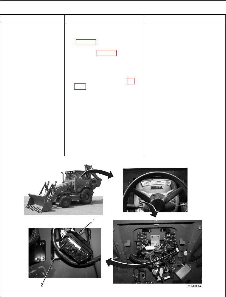
9. Disconnect front console wiring
harness connector (Figure 12,
Item 1) from front main chassis
wiring harness connector (Figure
12, Item 2).
Figure 12. Front Console Wiring Harness Connector.
0013