
TM 5-2420-231-23-1
0086
STEERING CONTROL VALVE TEST CONTINUED
8. Connect inlet hose (Figure 42, Item 1) to flowmeter (Figure 42, Item 3).
9. Connect outlet hose (Figure 42, Item 2) to flowmeter (Figure 42, Item 3).
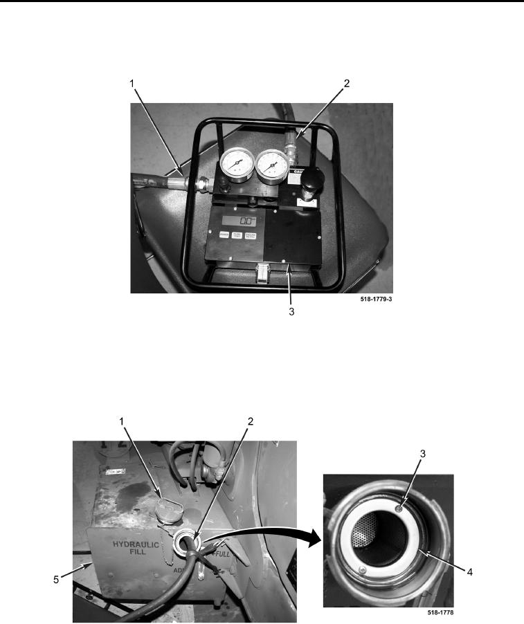
Figure 42. Flowmeter Connections.
0086
10. Remove cap (Figure 43, Item 1), two screws (Figure 43, Item 3), and screen (Figure 43, Item 4) from reservoir
(Figure 43, Item 5).
11. Insert outlet hose (Figure 43, Item 2) until it touches bottom of hydraulic reservoir (Figure 43, Item 5) and
secure hose in place.
Figure 43. Hydraulic Reservoir.
0086
12. Turn steering wheel to the straight ahead position.
13. Start and run engine at 2,000 rpm (TM 5-2420-231-10).