
TM 5-2420-231-23-2
0092
DISASSEMBLY CONTINUED
NOTE
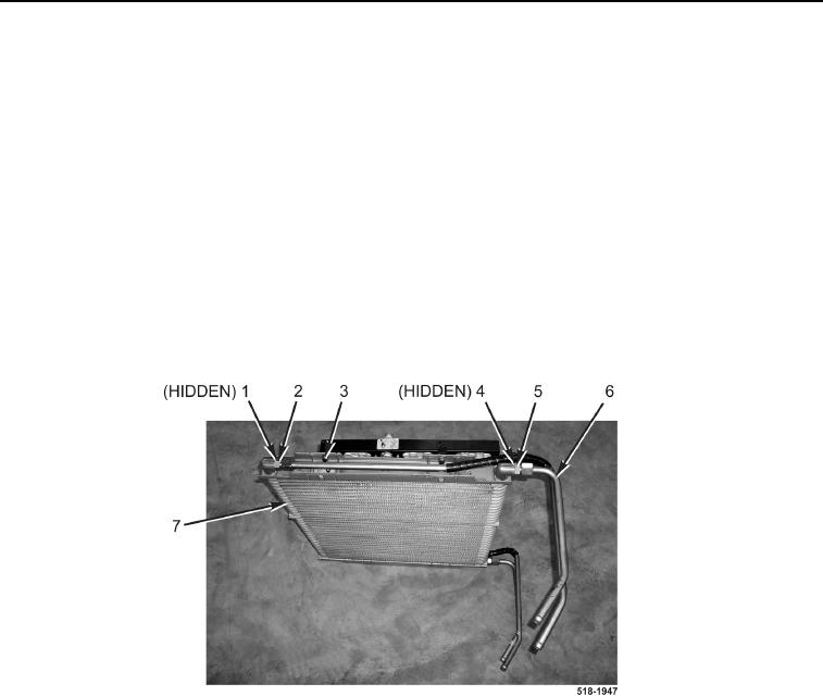
Note the location and orientation of cooling tubes to aid in assembly.
The procedure for cooling tube removal and replacement is identical for left-hand and
right-hand cooling tubes. Right-hand cooling tubes are shown in this procedure.
30. Remove oil cooler tube (Figure 25, Item 3) from transmission oil cooler outlet tube fitting (Figure 25, Item 2).
31. Remove oil cooler tube fitting (Figure 25, Item 2) and O-ring (Figure 25, Item 1) from transmission/hydraulic oil
cooler (Figure 25, Item 7). Discard O-ring.
32. Remove oil cooler tube (Figure 25, Item 6) from transmission oil cooler outlet tube fitting (Figure 25, Item 5).
33. Remove oil cooler tube fitting (Figure 25, Item 5) and O-ring (Figure 25, Item 4) from transmission/hydraulic oil
cooler (Figure 25, Item 7). Discard O-ring.
34. Repeat steps 30 through 33 for left side.
Figure 25. Transmission Oil Cooler Tubes.
0092