
TM 5-2420-231-23-2
0111
INSTALLATION CONTINUED
NOTE
Remove plugs and caps from hoses and fittings.
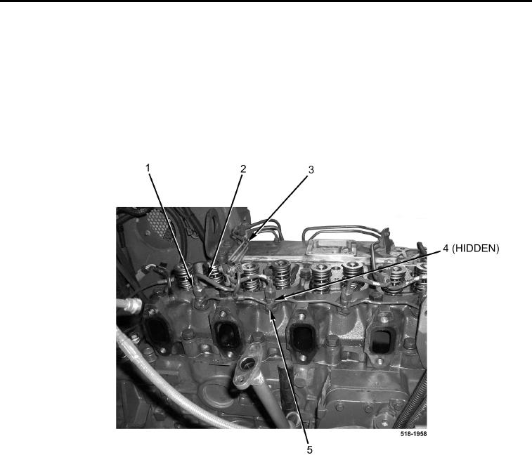
10. Position high-pressure fuel line assembly (Figure 22, Item 3) on machine.
11. Install four new injector return line crushwashers (Figure 22, Item 4) and bolts (Figure 22, Item 5) on fuel injec-
tors (Figure 22, Item 1).
12. Connect four high-pressure fuel lines (Figure 22, Item 2) to fuel injectors (Figure 22, Item 1).
Figure 22. High-Pressure Fuel Lines.
0111
13. Connect four high-pressure fuel lines (Figure 23, Item 10) to high-pressure fuel pump (Figure 23, Item 9).
14. Connect coolant hose (Figure 23, Item 8) and tighten clamp (Figure 23, Item 7) on cylinder head
(Figure 23, Item 6).
15. Connect wiring harness (Figure 23, Item 1) to cold start temperature switch (Figure 23, Item 2).
16. Install new crushwasher (Figure 23, Item 5), fuel return tube (Figure 23, Item 3), new crushwasher (Figure 23,
Item 4) and nut (Figure 23, Item 11) on high-pressure fuel pump (Figure 23, Item 9).