
TM 5-2420-231-23-2
0111
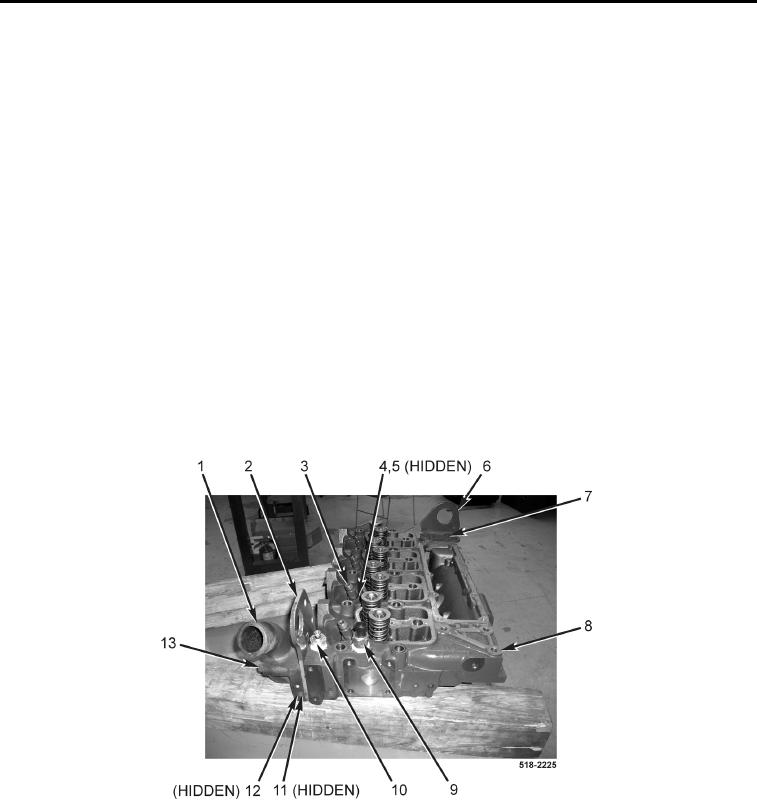
ASSEMBLY CONTINUED
NOTE
Install fuel injectors in position and orientation as noted during removal.
5. Install four fuel injectors (Figure 18, Item 3) on cylinder head (Figure 18, Item 8).
6. Install four new O-rings (Figure 18, Item 5) and fuel injector collars (Figure 18, Item 4) on cylinder head
(Figure 18, Item 8).
7. Wrap coolant temperature switch threads (Figure 18, Item 10) with teflon tape and install on cylinder head
(Figure 18, Item 8).
8. Wrap coolant temperature sensor threads (Figure 18, Item 9) with teflon tape and install on cylinder head
(Figure 18, Item 8).
9. Install rear lifting bracket (Figure 18, Item 6) and two bolts (Figure 18, Item 7) on cylinder head
(Figure 18, Item 8).
NOTE
Install thermostat bolts as noted during removal.
10. Install thermostat (Figure 18, Item 11), new gasket (Figure 18, Item 12), lifting bracket (Figure 18, Item 2), ther-
mostat housing (Figure 18, Item 1), and three bolts (Figure 18, Item 13) on cylinder head (Figure 18, Item 8).
Figure 18. Cylinder Head Components.
0111
END OF TASK