
TM 5-2420-231-23-2
0111
INSTALLATION CONTINUED
WARNING
Use caution when using adhesives and sealants. Prolonged inhalation of vapors can
cause lung irritation. Contact with skin can cause dermatitis. Wear gloves and safety
goggles and use product in a well-ventilated area away from open flame. If ingested, keep
individual calm and seek medical attention. DO NOT induce vomiting. If contact with skin
or eyes is made, flush thoroughly with water. Dispose of cleanup rags IAW local policy and
ordinances. Failure to follow this warning may cause injury to personnel.
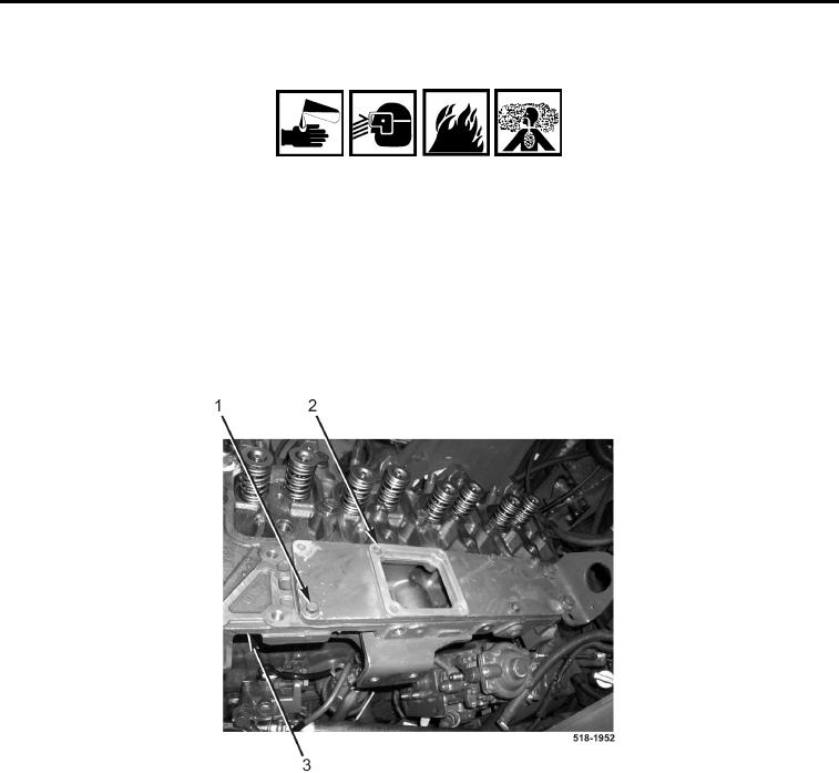
8. Apply a thin bead of silicone sealant to intake cover plate (Figure 21, Item 2).
9. Install four bolts (Figure 21, Item 1) and intake cover plate (Figure 21, Item 2) on cylinder head
(Figure 21, Item 3).
Figure 21. Intake Cover Plate.
0111