
TM 5-2420-231-23-2
0111
INSTALLATION CONTINUED
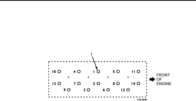
5. Tighten 14 cylinder head bolts (Figure 20, Item 1) to 30 lb-ft (40 Nm) in sequence shown.
6. Tighten 10 cylinder head bolts (Figure 20, Item 1) 1, 2, 4, 5, 7, 8, 10, 11, 13, and 14 to 37 lb-ft (50 Nm) in
sequence shown.
7. Finally, tighten 14 cylinder head bolts (Figure 20, Item 1) as indicated in sequence shown:
a. 3, 6, 9, and 12 an additional 90 degrees;
b. 1, 2, 4, 5, 7, 8, 10, 11, 13, and 14 an additional 180 degrees.
Figure 20. Cylinder Head Bolt Tightening Sequence.
0111