
TM 5-2420-231-23-2
0114
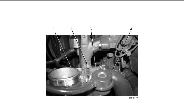
REMOVAL CONTINUED
2. Loosen clamp (Figure 2, Item 2), disconnect sleeve (Figure 2, Item 3) from turbocharger (Figure 2, Item 1), and
remove intake manifold (Figure 2, Item 4) from machine.
Figure 2. Clamp.
0114
NOTE
Tag and mark wires to aid in installation.
3. Remove three nuts (Figure 3, Items 1, 4, and 6), washer (Figure 3, Item 2), two wiring harness eyelets
(Figure 3, Items 5 and 9), and cable (Figure 3, Item 7) from grid heater (Figure 3, Item 8).
NOTE
Note position and orientation of grid heater to aid in installation.
4. Remove grid heater (Figure 3, Item 8) and two gaskets (Figure 3, Item 3) from air intake cover (Figure 3,
Item 10). Discard gaskets.