
TM 5-2420-231-23-2
0113
ADJUSTMENT
0113
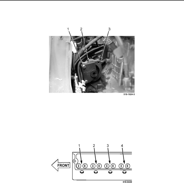
1. Install engine turning tool (Figure 4, Item 2) and two starter bolts (Figure 4, Item 1) on flywheel housing
(Figure 4, Item 3).
Figure 4. Engine Turning Tool.
0113
NOTE
The number 1 cylinder is at the front of the engine (closest to the radiator).
Manually rotate engine in a clockwise direction only.
2. Refer to Figure 5 to identify intake and exhaust valve arrangement.
Figure 5. Cylinder Identification.
0113
3. With assistance, rotate engine clockwise until the number 3 cylinder intake valve pushrod is at highest upward
travel and the number 1 intake and exhaust valve pushrods are at lowest downward travel.