TM 5-2420-231-23-2
0113
ADJUSTMENT CONTINUED
NOTE
Refer to Table 1 to identify which valves to adjust, as indicated by "X".
Set intake valve lash to 0.012 in. (0.30 mm).
Set exhaust valve lash to 0.022 in. (0.55 mm).
Table 1. Valve Lash Adjustment.
0113
Cylinder
1
2
3
4
0113
0113
0113
0113
0113
Intake
X
X
Exhaust
X
X
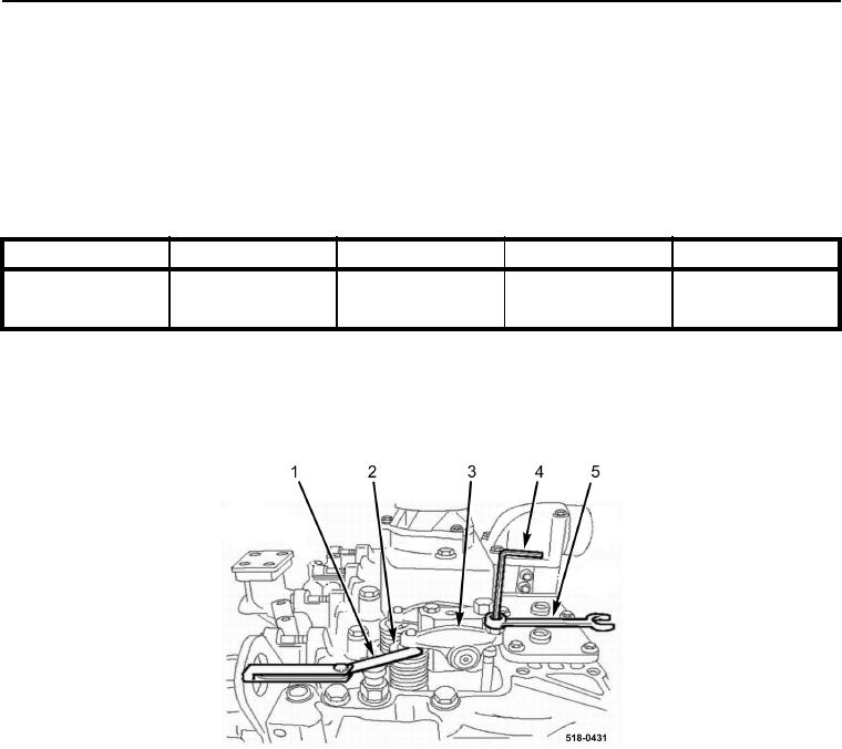
4. Insert feeler gauge (Figure 6, Item 1) between rocker arm (Figure 6, Item 3) and valve tip (Figure 6, Item 2).
Adjust valve adjustment screw (Figure 6, Item 4) until correct valve lash is achieved.
5. Hold valve adjustment screw (Figure 6, Item 4) while tightening valve adjustment screw jamnut
(Figure 6, Item 5).
Figure 6. Valve Adjustment.
0113
6. Recheck valve lash.
7. Repeat steps 4 through 6 until all valves have been adjusted and rechecked in accordance with Table 1.
8. With assistance, rotate engine clockwise one complete revolution until number 1 intake valve pushrod is at
highest upward travel and number 4 intake valve and exhaust valve pushrods are at lowest downward travel.

