
TM 5-2420-231-23-2
0166
ADJUSTMENT
0166
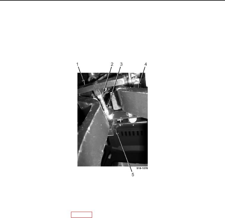
With brake pedals (Figure 4, Item 4) released, brake switch bolt (Figure 4, Item 3) should open brake light switch
(Figure 4, Item 5). To adjust brake light switch:
a. Loosen jamnut (Figure 4, Item 2).
b. Turn brake switch bolt (Figure 4, Item 3) counter clockwise in brake lamp arm (Figure 4, Item 1) until brake
light switch (Figure 4, Item 5) is open.
c.
Tighten jamnut (Figure 4, Item 2).
Figure 4. Brake Light Switch Adjustment.
0166
END OF TASK
FOLLOW-ON TASKS
0166
Install instrument panel front cover (WP 0174).
END OF TASK
END OF WORK PACKAGE