
TM 5-2420-231-23-2
0174
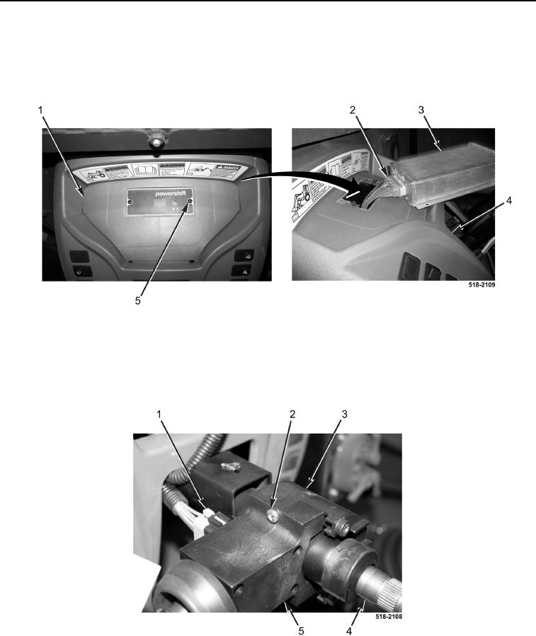
INSTALLATION CONTINUED
12. Install access cover (Figure 16, Item 1) on instrument panel (Figure 16, Item 4).
13. Connect electrical connector (Figure 16, Item 2) to ECM (Figure 16, Item 3).
14. Install ECM (Figure 16, Item 3) and two screws (Figure 16, Item 5) on access cover (Figure 16, Item 1).
Figure 16. Access Cover.
0174
15. Install left-side FNR selector switch (Figure 17, Item 5), right-side FNR selector switch (Figure 17, Item 3), and
two screws (Figure 17, Item 2) on steering column (Figure 17, Item 4).
16. Connect electrical connector (Figure 17, Item 1) to left-side FNR selector switch (Figure 17, Item 5).
Figure 17. FNR Selector Switch.
0174