
TM 5-2420-231-23-2
0174
INSTALLATION CONTINUED
21. Position turn signal switch (Figure 20, Item 3) in upper and lower cover (Figure 20, Item 1).
22. Install two screws (Figure 20, Item 2) on cover (Figure 20, Item 1).
Figure 20. Turn Signal Switch.
0174
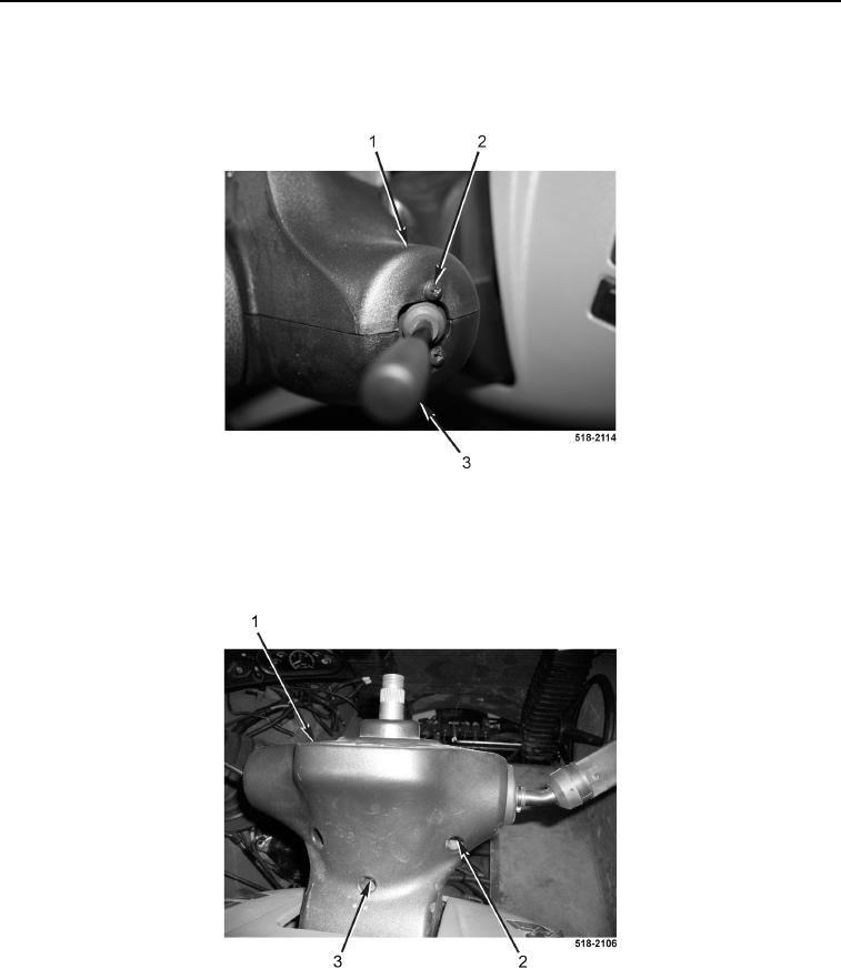
23. Install two screws (Figure 21, Item 2) on top cover (Figure 21, Item 1).
24. Install screw (Figure 21, Item 3) on top cover (Figure 21, Item 1).
Figure 21. Top Cover Screws.
0174