
TM 5-2420-231-23-2
0226
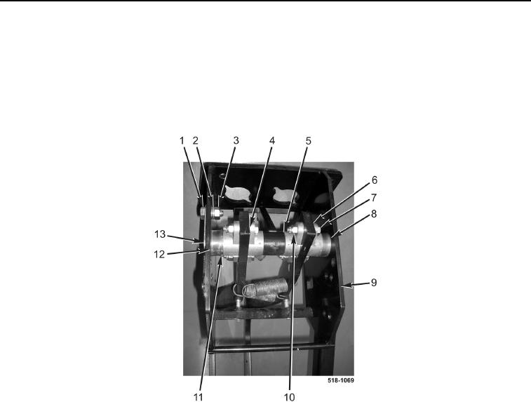
ASSEMBLY CONTINUED
13. Install brake pedal rod (Figure 16, Item 13), spacer (Figure 16, Item 12), washer (Figure 16, Item 11), left brake
pedal (Figure 16, Item 4), brake lamp arm (Figure 16, Item 5), right brake pedal (Figure 16, Item 6), and spacer
(Figure 16, Item 8) on brake pedal bracket (Figure 16, Item 9).
14. Install bolt (Figure 16, Item 1), new lockwasher (Figure 16, Item 2), and nut (Figure 16, Item 3) on brake pedal
bracket (Figure 16, Item 9).
15. Tighten four bolts (Figure 16, Item 7) and locknuts (Figure 16, Item 10).
Figure 16. Brake Pedal Rod.
0226