
TM 5-2420-231-23-3
0263
INSTALLATION CONTINUED
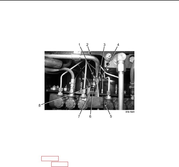
41. Position boom lock lever bracket (Figure 17, Item 5) on machine.
42. Install two washers (Figure 17, Item 8), new lockwashers (Figure 17, Item 7), and bolts (Figure 17, Item 6) on
boom lock lever bracket (Figure 17, Item 5).
43. Install pin (Figure 17, Item 1), washer (Figure 17, Item 3), and new cotter pin (Figure 17, Item 4) on boom lock
lever (Figure 17, Item 2).
Figure 17. Boom Lock Lever.
0263
44. Install cap on hydraulic tank (TM 5-2420-231-10).
END OF TASK
FOLLOW-ON TASKS
0263
1. Install rear cab cover (WP 0326).
2. Install rear floor cover plate (WP 0306).
3. Check hydraulic oil level and fill as necessary (TM 5-2420-231-10).
END OF TASK
END OF WORK PACKAGE
0263-17/(18 blank)