TM 5-2420-231-23-3
0264
ASSEMBLY
0264
NOTE
Install hoses, tubes, and fittings in position and orientation noted during removal.
Remove plugs and caps from fittings prior to installation.
1. Install new O-ring (Figure 4, Item 13) and accumulator (Figure 4, Item 12) on pilot control valve assembly
(Figure 4, Item 1).
2. Install new O-ring (Figure 4, Item 8) and straight fitting (Figure 4, Item 9) on pilot control valve assembly
(Figure 4, Item 1).
3. Install new O-ring (Figure 4, Item 6) and hydraulic test port (Figure 4, Item 5) on pilot control valve assembly
(Figure 4, Item 1).
4. Install new O-ring (Figure 4, Item 11) and tee fitting (Figure 4, Item 7) on pilot control valve assembly
(Figure 4, Item 1) and tighten nut (Figure 4, Item 10).
5. Install new O-ring (Figure 4, Item 3) and 90-degree fitting (Figure 4, Item 4) on pilot control valve assembly
(Figure 4, Item 1) and tighten nut (Figure 4, Item 2).
6. Install 14 new O-rings (Figure 4, Item 14) and straight fittings (Figure 4, Item 15) on pilot control valve
assembly (Figure 4, Item 1).
END OF TASK
INSTALLATION
0264
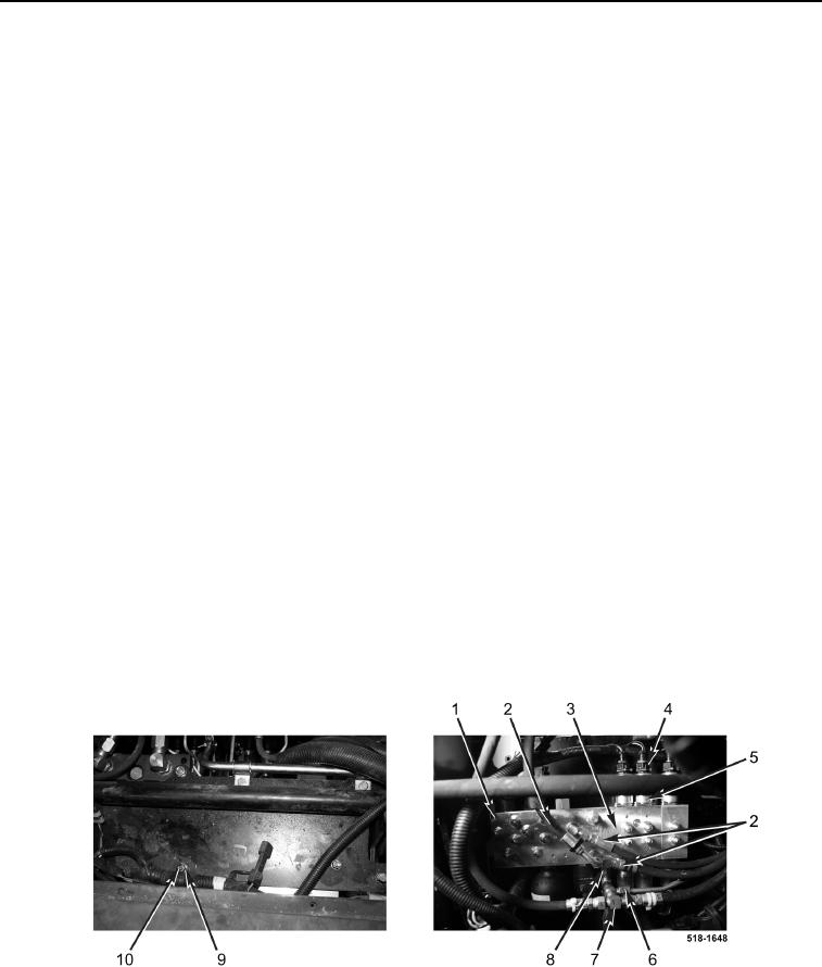
1. Install pilot control valve assembly (Figure 5, Item 3), two capscrews (Figure 5, Item 1), washers (Figure 5,
Item 9), and new locknuts (Figure 5, Item 10) on machine.
2. Connect nine wiring harness connectors (Figure 5, Item 4) to pilot control valve solenoids (Figure 5, Item 5).
3. Connect tee (Figure 5, Item 8) to pilot control valve assembly (Figure 5, Item 3).
4. Connect tube (Figure 5, Item 6) to fitting (Figure 5, Item 7).
5. Connect three hydraulic hoses (Figure 5, Item 2) to pilot control valve assembly (Figure 5, Item 3).
Figure 5. Pilot Control Valve.
0264

