
TM 5-2420-231-23-3
0264
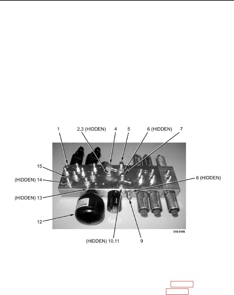
DISASSEMBLY
0264
NOTE
Note position and orientation of fittings to aid in installation.
1. Remove 14 straight fittings (Figure 4, Item 15) and O-rings (Figure 4, Item 14) from pilot control valve
assembly (Figure 4, Item 1). Discard O-rings.
2. Loosen nut (Figure 4, Item 2) and remove 90-degree fitting (Figure 4, Item 4) and O-ring (Figure 4, Item 3) from
pilot control valve assembly (Figure 4, Item 1). Discard O-ring.
3. Loosen nut (Figure 4, Item 10) and remove tee fitting (Figure 4, Item 7) and O-ring (Figure 4, Item 11) from pilot
control valve assembly (Figure 4, Item 1). Discard O-ring.
4. Remove hydraulic test port (Figure 4, Item 5) and O-ring (Figure 4, Item 6) from pilot control valve assembly
(Figure 4, Item 1). Discard O-ring.
5. Remove straight fitting (Figure 4, Item 9) and O-ring (Figure 4, Item 8) from pilot control valve assembly
(Figure 4, Item 1). Discard O-ring.
6. Remove accumulator (Figure 4, Item 12) and O-ring (Figure 4, Item 13) from pilot control valve assembly
(Figure 4, Item 1). Discard O-ring.
Figure 4. Pilot Control Valve Assembly.
0264
END OF TASK
CLEANING AND INSPECTION
0264
1. Clean and inspect all parts IAW Mechanical General Maintenance Instructions (WP 0369).
2. Clean and inspect all parts IAW Electrical General Maintenance Instructions (WP 0370).
END OF TASK