
TM 5-2420-231-23-3
0263
INSTALLATION CONTINUED
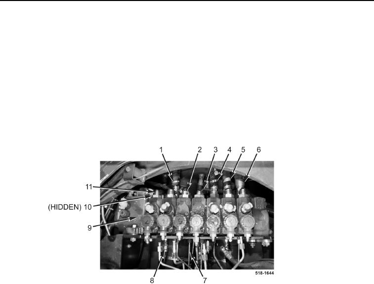
23. Connect hydraulic hose (Figure 14, Item 6), hydraulic hose (Figure 14, Item 5), hydraulic hose (Figure 14,
Item 4), hose (Figure 14, Item 3), hose (Figure 14, Item 2), and hydraulic hose (Figure 14, Item 1) to backhoe
control valve assembly (Figure 14, Item 9).
NOTE
Install fittings in position and orientation noted during removal.
24. Install six new O-rings (Figure 14, Item 10) and fittings (Figure 14, Item 11) on backhoe control valve
(Figure 14, Item 9).
25. Connect two hydraulic hoses (Figure 14, Item 8) and five tubes (Figure 14, Item 7) to backhoe control valve
assembly (Figure 14, Item 9).
Figure 14. Bottom Row Connections at Backhoe Control Valve.
0263