
TM 5-2420-231-23-3
0263
INSTALLATION CONTINUED
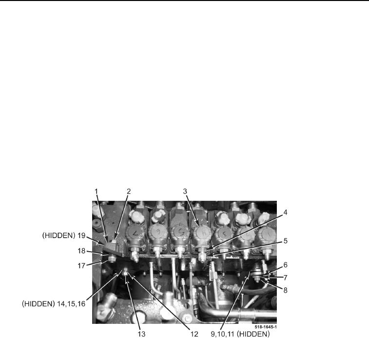
13. Install washer (Figure 12, Item 15), bolt (Figure 12, Item 14), spacer (Figure 12, Item 16), new lockwasher
(Figure 12, Item 12), and nut (Figure 12, Item 13) on backhoe control valve assembly (Figure 12, Item 3). Do
not tighten at this time.
14. Remove bolt (Figure 12, Item 2) and nut (Figure 12, Item 17) from backhoe control valve assembly
(Figure 12, Item 3).
15. Install washer (Figure 12, Item 1), bolt (Figure 12, Item 2), spacer (Figure 12, Item 19), new lockwasher
(Figure 12, Item 18), and nut (Figure 12, Item 17) on backhoe control valve assembly (Figure 12, Item 3). Do
not tighten at this time.
16. Remove bolt (Figure 12, Item 9) and nut (Figure 12, Item 8) from backhoe control valve assembly
(Figure 12, Item 3).
17. Install washer (Figure 12, Item 10), bolt (Figure 12, Item 9), spacer (Figure 12, Item 11), washer (Figure 12,
Item 7), new lockwasher (Figure 12, Item 5), and nut (Figure 12, Item 8) on backhoe control valve assembly
(Figure 12, Item 3).
18. Tighten nuts (Figure 12, Items 13 and 17) on backhoe control valve assembly (Figure 12, Item 3).
19. Loosen nut (Figure 12, Item 4) and rotate fitting (Figure 12, Item 6) 180 degrees clockwise. Tighten nut.
Figure 12. Bolts.
0263