
TM 5-2420-231-23-3
0264
INSTALLATION CONTINUED
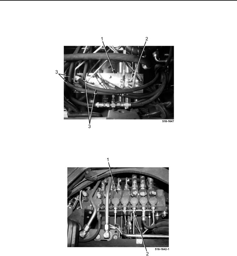
6. Connect four hydraulic hoses (Figure 6, Item 3) to pilot control valve assembly (Figure 6, Item 1).
7. Install and connect 10 tubes (Figure 6, Item 2) to pilot control valve assembly (Figure 6, Item 1).
Figure 6. Tubes and Hoses.
0264
8. Connect 10 tubes (Figure 7, Item 2) to front side of backhoe control valve assembly (Figure 7, Item 1).
Figure 7. Backhoe Control Valve.
0264
9. Install cap on hydraulic tank (TM 5-2420-231-10).
END OF TASK