
TM 5-2420-231-23-3
0266
REMOVAL
0266
1. Remove cap from hydraulic tank (TM 5-2420-231-10).
NOTE
The procedure for joystick control valve removal and replacement is identical for left-hand
and right-hand joystick control valves. Left-hand joystick control valve is shown in this
procedure.
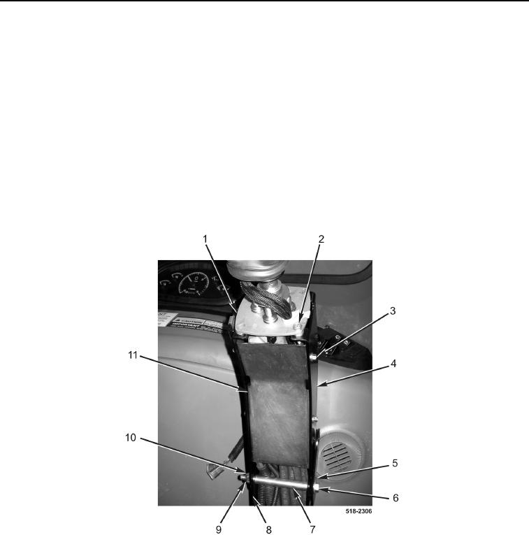
2. Remove four bolts (Figure 1, Item 3) and cover (Figure 1, Item 11) from upper joystick tower (Figure 1, Item 4).
3. Remove two bolts (Figure 1, Item 2) from left joystick control valve (Figure 1, Item 1) and upper joystick tower
(Figure 1, Item 4).
4. Remove locknut (Figure 1, Item 10), washer (Figure 1, Item 9), bolt (Figure 1, Item 6), washer (Figure 1,
Item 5), spacer (Figure 1, Item 7), and upper joystick tower (Figure 1, Item 4) from lower joystick tower
(Figure 1, Item 8). Discard locknut.
Figure 1. Left Joystick Tower.
0266