
TM 5-2420-231-23-3
0266
DISASSEMBLY
0266
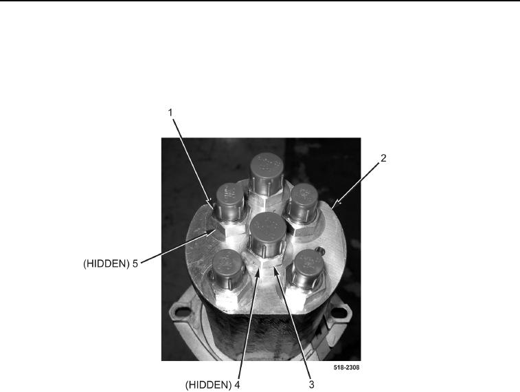
1. Remove four fittings (Figure 3, Item 1) and O-rings (Figure 3, Item 5) from left joystick control valve
(Figure 3, Item 2). Discard O-rings.
2. Remove two fittings (Figure 3, Item 3) and O-rings (Figure 3, Item 4) from left joystick control valve
(Figure 3, Item 2). Discard O-rings.
Figure 3. Left Joystick Control Valve Fittings.
0266
3. Remove three screws (Figure 4, Item 2) from grip handle (Figure 4, Item 1).
4. Remove two grip handle halves (Figure 4, Item 1) from joystick control valve (Figure 4, Item 5).
NOTE
Note quantity and location of tiedown straps to aid in installation.
5. Remove tiedown straps (Figure 4, Item 3) from AUX control switches wiring harness (Figure 4, Item 4). Discard
tiedown straps.