
TM 5-2420-231-23-3
0266
DISASSEMBLY CONTINUED
NOTE
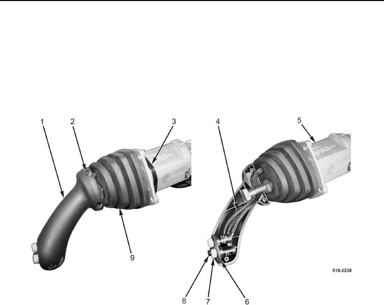
Note position and orientation of AUX control and horn switches to aid in installation.
6. Remove two AUX control switches (Figure 4, Item 7) and horn switch (Figure 4, Item 8) from bezel
(Figure 4, Item 6).
7. Route two AUX control switches (Figure 4, Item 7) and horn switch (Figure 4, Item 8) through joystick boot
(Figure 4, Item 9).
Figure 4. Grip Handle.
0266