
TM 5-2420-231-23-3
0266
ASSEMBLY
000266
NOTE
Install lines and wires as tagged and marked during removal.
Remove plugs and caps from hoses and fittings.
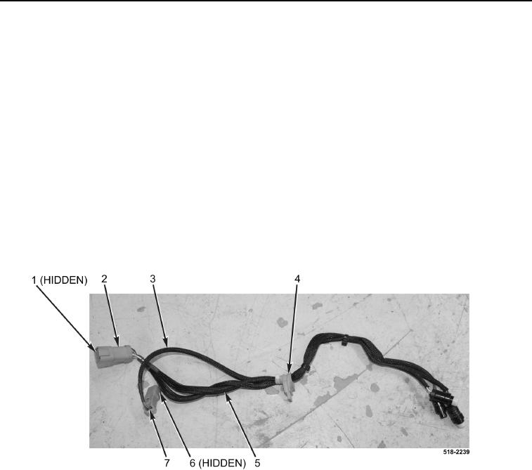
1. Install AUX control switches harness and horn switch harness (Figure 6, Items 2 and 7) through grommet
(Figure 6, Item 4).
NOTE
Install harness connector pins in position noted during removal.
2. Install six harness connector pins (Figure 6, Item 5) on AUX control harness connector (Figure 6, Item 2).
3. Install locking wedge (Figure 6, Item 1) on AUX control switches harness connector (Figure 6, Item 2).
4. Install two harness connector pins (Figure 6, Item 3) on horn switch harness connector (Figure 6, Item 6).
5. Install locking wedge (Figure 6, Item 6) on horn switch harness connector (Figure 6, Item 7).
Figure 6. AUX Control Switches.
0266