
TM 5-2420-231-23-3
0267
REMOVAL CONTINUED
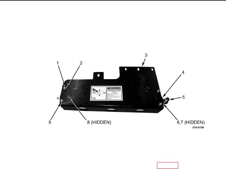
8. Loosen nut (Figure 2, Item 6) and remove fitting (Figure 2, Item 5) and O-ring (Figure 2, Item 7) from ride con-
trol accumulator (Figure 2, Item 4). Discard O-ring.
9. Remove four nuts (Figure 2, Item 1), lockwashers (Figure 2, Item 2), two U-bolts (Figure 2, Item 9), saddles
(Figure 2, Item 8), and ride control accumulator (Figure 2, Item 4) from bracket (Figure 2, Item 3).
Discard lockwashers.
Figure 2. Ride Control Accumulator Bracket.
0267
END OF TASK
CLEANING AND INSPECTION
0267
Clean and inspect all parts IAW Mechanical General Maintenance Instructions (WP 0369).
END OF TASK
INSTALLATION
0267
NOTE
Remove plugs and caps from hoses and fittings.
1. Install accumulator (Figure 2, Item 4), two saddles (Figure 2, Item 8), U-bolts (Figure 2, Item 9), four new lock-
washers (Figure 2, Item 2), and nuts (Figure 2, Item 1) on bracket (Figure 2, Item 3).
2. Install new O-ring (Figure 2, Item 7) and fitting (Figure 2, Item 5) on ride control accumulator (Figure 2, Item 4)
and tighten nut (Figure 2, Item 6).