
TM 5-2420-231-23-3
0267
REMOVAL
0267
1. Remove cap from hydraulic oil tank (TM 5-2420-231-10).
2. With engine off and ride control off, maneuver front end loader joystick through several different positions to
relieve system pressure.
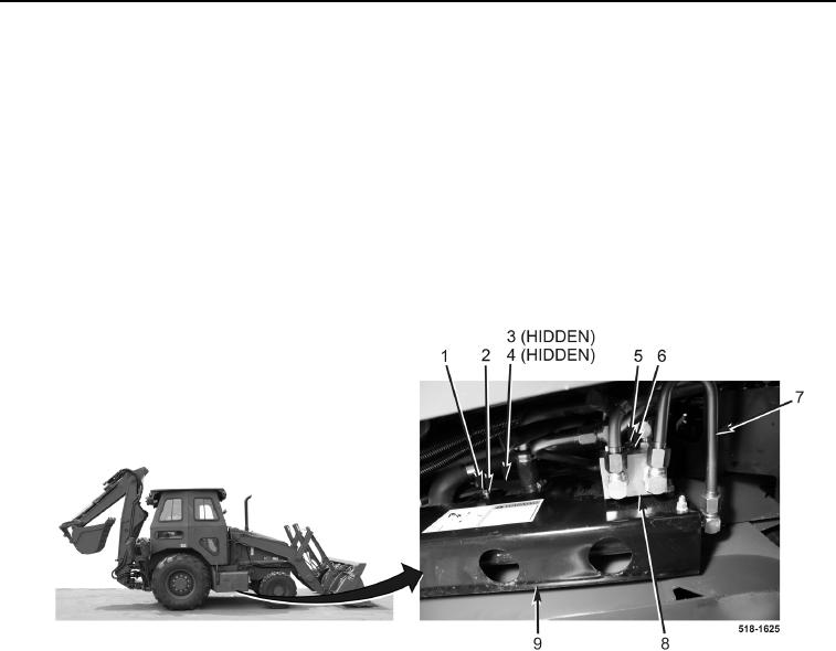
3. Disconnect tube (Figure 1, Item 7) from ride control solenoid valve (Figure 1, Item 8).
4. Disconnect tube (Figure 1, Item 7) from ride control accumulator (Figure 1, Item 9).
5. Remove tube (Figure 1, Item 7) from machine.
6. Remove bolt (Figure 1, Item 5) and washer (Figure 1, Item 6) from ride control solenoid valve
(Figure 1, Item 8).
7. Remove two bolts (Figure 1, Item 1), washers (Figure 1, Item 2), ride control accumulator (Figure 1, Item 9),
two spacers (Figure 1, Item 3), and O-rings (Figure 1, Item 4) from machine. Discard O-rings.
Figure 1. Ride Control Accumulator.
0267