
TM 5-2420-231-23-3
0266
INSTALLATION CONTINUED
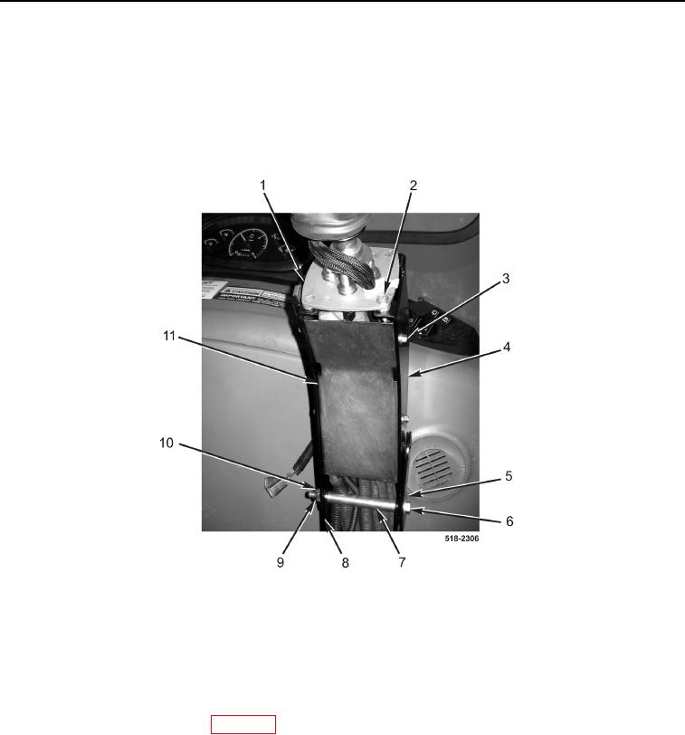
5. Install upper joystick tower (Figure 10, Item 4), spacer (Figure 10, Item 7), washer (Figure 10, Item 5), bolt
(Figure 10, Item 6), washer (Figure 10, Item 9), and new locknut (Figure 10, Item 10) on lower joystick tower
(Figure 10, Item 8).
6. Install left joystick control valve (Figure 10, Item 1) and two bolts (Figure 10, Item 2) on upper joystick tower
(Figure 10, Item 4).
7. Install cover (Figure 10, Item 11) and four bolts (Figure 10, Item 3) on upper joystick tower (Figure 10, Item 4).
Figure 10. Left Joystick Tower.
0266
8. Install cap on hydraulic tank (TM 5-2420-231-10).
END OF TASK
FOLLOW-ON TASKS
0266
Install backhoe control tower boot (WP 0287).
END OF TASK
END OF WORK PACKAGE
0266-11/(12 blank)