
TM 5-2420-231-23-3
0266
INSTALLATION
0266
NOTE
The procedure for joystick control valve removal and replacement is identical for left-hand
and right-hand joystick control valves. Left-hand joystick control valve is shown in this
procedure.
Install hoses in position and orientation noted during removal.
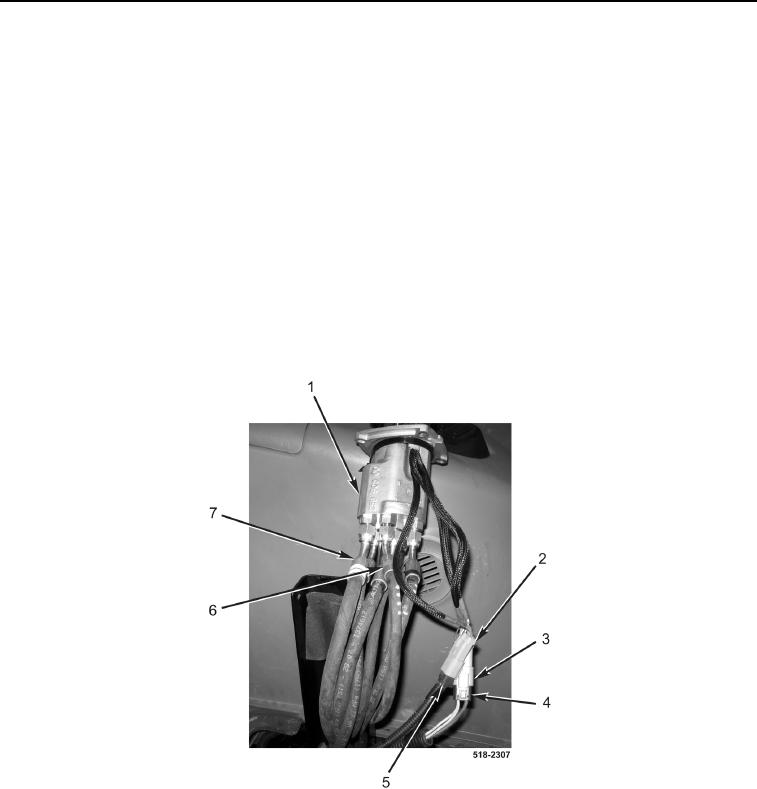
1. Connect two hoses (Figure 9, Item 7) to left joystick control valve (Figure 9, Item 1).
2. Connect four hoses (Figure 9, Item 6) to left joystick control valve (Figure 9, Item 1).
NOTE
Steps 3 and 4 are for left-hand joystick control valve only.
3. Connect left joystick control connector (Figure 9, Item 3) to harness connector (Figure 9, Item 4).
4. Connect left joystick control connector (Figure 9, Item 2) to harness connector (Figure 9, Item 5).
Figure 9. Left Joystick Control Valve.
0266