
TM 5-2420-231-23-3
0270
REMOVAL CONTINUED
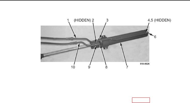
Figure 2. Loader Bucket Cylinder Tubes.
0270
END OF TASK
CLEANING AND INSPECTION
0270
Clean and inspect all parts IAW Mechanical General Maintenance Instructions (WP 0369).
END OF TASK
INSTALLATION
0270
NOTE
Install lines as tagged and marked during removal.
Remove plugs and caps from hoses and fittings.
1. Install new O-ring (Figure 2, Item 5) and fitting (Figure 2, Item 6) on loader bucket cylinder (Figure 2, Item 7)
and tighten nut (Figure 2, Item 4).
2. Install new O-ring (Figure 2, Item 2) and fitting (Figure 2, Item 9) on loader bucket cylinder (Figure 2, Item 7).
3. Connect tube (Figure 2, Item 1) to fitting (Figure 2, Item 6).
4. Install resilient mount (Figure 2, Item 8) and clamp (Figure 2, Item 3) on loader bucket cylinder
(Figure 2, Item 7).
5. Connect tube (Figure 2, Item 10) to fitting (Figure 2, Item 9).