
TM 5-2420-231-23-3
0277
ASSEMBLY CONTINUED
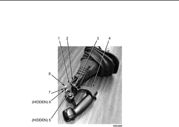
20. Install manual control lever (Figure 25, Item 4), washer (Figure 25, Item 5), spacer (Figure 25, Item 6), washer
(Figure 25, Item 7), and bolt (Figure 25, Item 8) on manual control bracket (Figure 25, Item 1).
21. Install rod (Figure 25, Item 2) and new retaining ring (Figure 25, Item 3) on manual control lever
(Figure 25, Item 4).
Figure 25. Manual Control Lever.
0277
END OF TASK