
TM 5-2420-231-23-3
0277
INSTALLATION
0277
NOTE
Install rods in position and orientation noted during removal.
1. Install three rods (Figure 26, Item 2), clevis pins (Figure 26, Item 3), and new cotter pins (Figure 26, Item 1) on
machine.
Figure 26. Rods.
0277
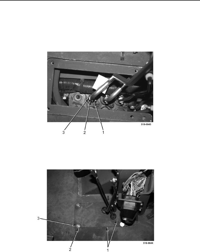
2. Install two floor plates (Figure 27, Item 1), four washers (Figure 27, Item 2), and bolts (Figure 27, Item 3) on
machine.
Figure 27. Floor Plates.
0277