
TM 5-2420-231-23-3
0278
INSTALLATION CONTINUED
NOTE
Install wires as tagged and marked during removal.
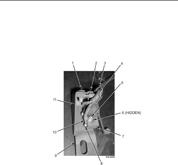
4. Connect two wires (Figure 17, Item 10) to switch (Figure 17, Item 7), and install two screws (Figure 17, Item 8).
5. Install switch (Figure 17, Item 7), two screws (Figure 17, Item 6), new locknuts (Figure 17, Item 5) on switch
(Figure 17, Item 7).
6. Install clamp (Figure 17, Item 3) and bolt (Figure 17, Item 2) on wiring harness (Figure 17, Item 4).
7. Install cover (Figure 17, Item 11) and bolt (Figure 17, Item 1) on bracket (Figure 17, Item 9).
Figure 17. Switch.
0278