
TM 5-2420-231-23-3
0279
REMOVAL
0279
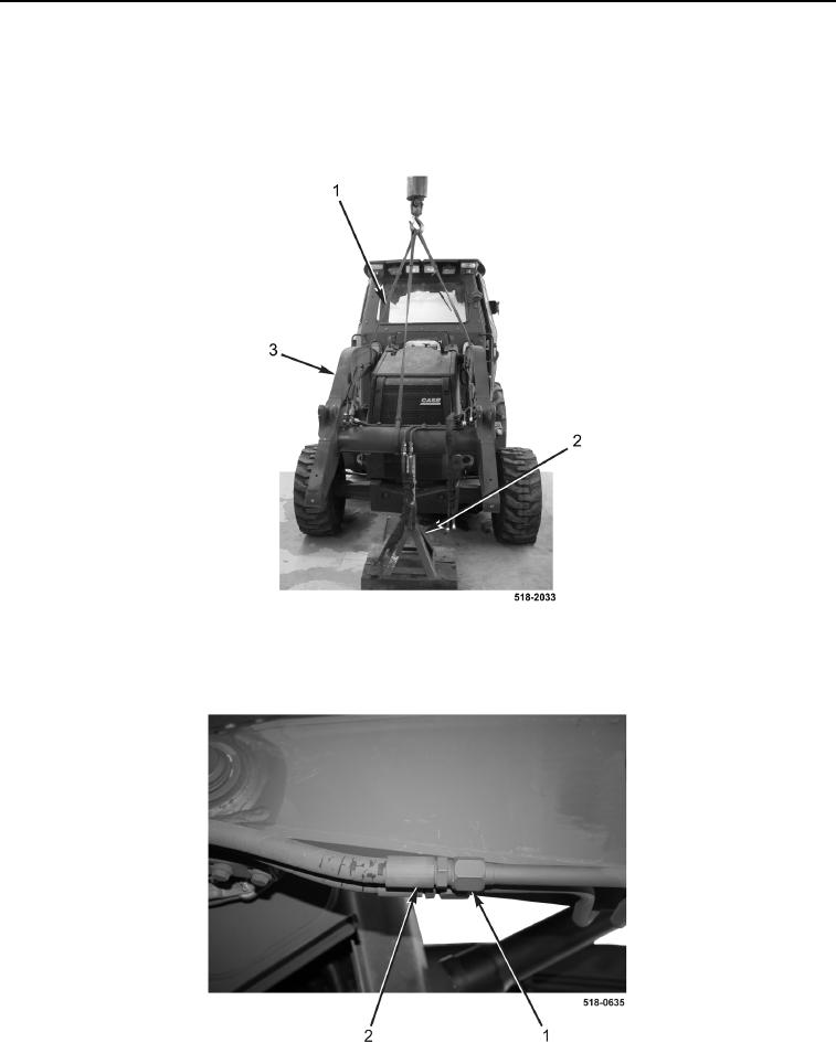
1. Attach three slings (Figure 1, Item 1) and lifting device to lift frame (Figure 1, Item 3).
2. Using lifting device, raise lift frame until fully extended trestle (Figure 1, Item 2) and cribbing can be placed
under lift frame.
3. Lower lift frame (Figure 1, Item 3) onto trestle.
Figure 1. Lift Frame.
0279
4. Disconnect two hoses (Figure 2, Item 2) from tubes (Figure 2, Item 1) on right side of loader.
Figure 2. Hoses and Tubes (Right Side).
0279