
TM 5-2420-231-23-3
0286
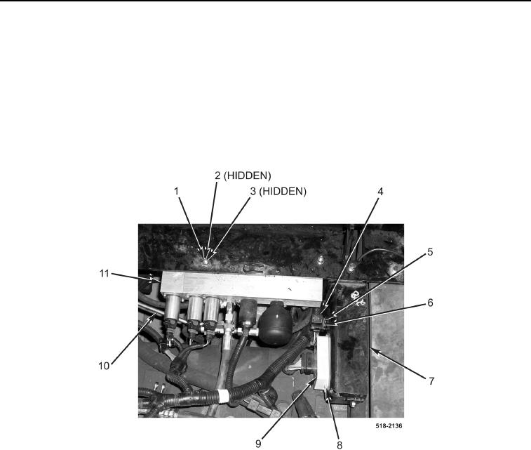
REMOVAL CONTINUED
32. Disconnect tube (Figure 10, Item 10) from pilot control valve (Figure 10, Item 11).
33. Remove relay (Figure 10, Item 4) from relay connector (Figure 10, Item 6).
34. Remove screw (Figure 10, Item 5) and relay connector (Figure 10, Item 6) from backhoe control tower bracket
(Figure 10, Item 7).
35. Remove two screws (Figure 10, Item 8) and pilot control ECU (Figure 10, Item 9) from backhoe control tower
bracket (Figure 10, Item 7). Set pilot control ECU aside.
36. Remove two locknuts (Figure 10, Item 1), four washers (Figure 10, Item 2), and two bolts (Figure 10, Item 3)
from pilot control valve (Figure 10, Item 11). Set pilot control valve aside. Discard locknuts.
Figure 10. Pilot Control Valve.
0286