
TM 5-2420-231-23-3
0286
DISASSEMBLY CONTINUED
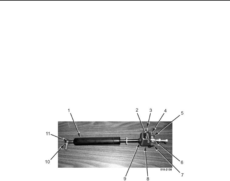
10. Remove clip (Figure 14, Item 11) and pivot (Figure 14, Item 10) from piston (Figure 14, Item 1).
11. Remove locknut (Figure 14, Item 4), bolt (Figure 14, Item 7), two spacers (Figure 14, Item 5), and pivot
(Figure 14, Item 6) from bracket (Figure 14, Item 8). Discard locknut.
NOTE
Note position and orientation of channel to aid in installation.
12. Remove cotter pin (Figure 14, Item 3) and channel (Figure 14, Item 2) from bracket (Figure 14, Item 8). Discard
cotter pin.
NOTE
Note adjustment of piston rod to aid in assembly.
13. Loosen jamnut (Figure 14, Item 9) and remove bracket (Figure 14, Item 8) from piston (Figure 14, Item 1).
Figure 14. Backhoe Control Tower Piston.
0286