TM 5-2420-231-23-3
0286
DISASSEMBLY
0286
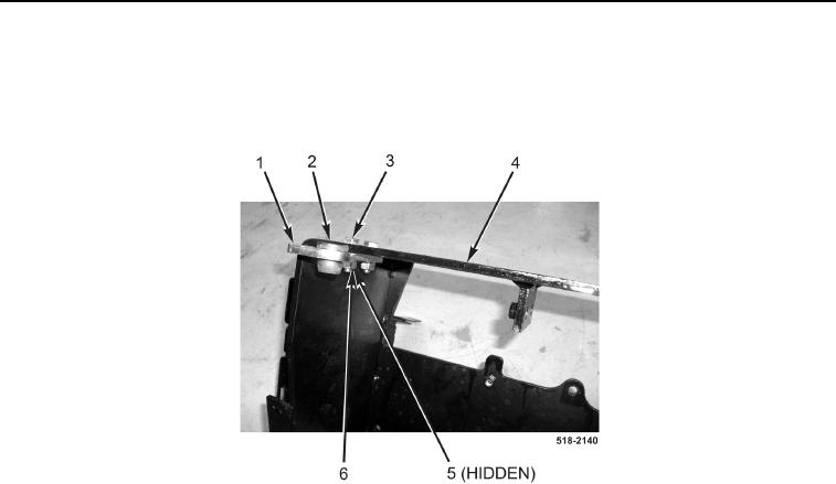
1. Remove two nuts (Figure 12, Item 6), lockwashers (Figure 12, Item 5), bolts (Figure 12, Item 3), and mounting
bracket (Figure 12, Item 1) from backhoe control tower (Figure 12, Item 4). Discard lockwashers.
2. Remove isolator (Figure 12, Item 2) from mounting bracket (Figure 12, Item 1).
Figure 12. Mounting Bracket.
0286
NOTE
Note adjustment on lock cable to aid in assembly.
Note routing of cable to aid in assembly.
3. Loosen jamnut (Figure 13, Item 11) on cable (Figure 13, Item 1).
4. Remove cotter pin (Figure 13, Item 9) from release bracket (Figure 13, Item 10). Discard cotter pin.
5. Disconnect cable (Figure 13, Item 1) from release bracket (Figure 13, Item 10), and remove cable from back-
hoe control tower (Figure 13, Item 4).
6. Remove locknut (Figure 13, Item 3) from piston pivot (Figure 13, Item 2). Discard locknut.
NOTE
Note adjustment on bracket bolt to aid in assembly.
7. Remove nut (Figure 13, Item 7) and lockwasher (Figure 13, Item 6) from piston bracket bolt (Figure 13, Item 5).
Discard lockwasher.

